This post is also available in: Japanese
1.Introduction
Hot cathode ionization vacuum gauges used for measuring pressure in a high vacuum range have been causing a growing number of problems in recent years. Hot cathode ionization vacuum gauges exhibit low or fluctuating readings, and cold cathode ionization vacuum gauges often fail to discharge electricity. Users, noticing low or fluctuating readings, are likely to think that the problem is caused by life time and replace it. These problems are attested by the “Report on the Results of Questionnaire about Role of Vacuum Gauges and Vacuum Standard”1), which says that more and more users are calling for accurate and stable vacuum gauges. This paper reports on the development of an ionization vacuum gauge with a gauge head that has improved stability and that satisfies the demand for accurate and stable vacuum gauges.
2.Problems with the cold cathode ionization vacuum gauge and the B-A ionization vacuum gauge
A metal material, such as stainless steel, is used for manufacturing the vacuum chambers of vacuum equipment. The type of cutting fluid used for processing this metal material has recently been changed from cutting oil to a water-soluble type due to the demand to reduce environmental loads. Since the end of 1995, when the production of CFC, an ozone-depleting substance, was abolished, fluorocarbon-based cleaning agents used for cleaning processed materials have been changed to environmental load-reducing water-based or hydrocarbon-based cleaning agents. It was from that time that cutting fluid and cleaning agent residue started to be observed inside chambers.
*1 This paper is a revision of “Journal of the Vacuum Society of Japan, 59 (2016) 9, 245-247”.
Immediately after the vacuum equipment starts operation, the residue generates gas, which often lowers the readings of cold cathode ionization vacuum gauges and a B-A ionization vacuum gauges. Also, there are cases in which applying vacuum grease on the O-ring of a gauge-head connecting flange as shown in Figure 1, and using an O- ring made of nitrile rubber instead of fluororubber resulted in lowering readings. In addition, many recent devices manufactured through vacuum processes use new materials such as films, acrylic substrates, and organic EL materials. These materials also generate gas that lead to lowered readings.
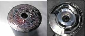
As the cold cathode ionization vacuum gauge utilizes electric discharge to provide an pumping effect larger than that of the hot cathode ionization vacuum gauge, organic materials tend to be deposited on its electrode in the environment described earlier. This can cause unstable discharge leading to unstable readings and, eventually, discharge extinction 2). An oil diffusion pump was modified by removing a baffle to let oil climb the pipe, and an electrode was operated just above this pump. Figure 2(a) is a photograph of this electrode. It shows carbide sticking to the electrode surface. If a pressure to be measured is near the upper measurable limit, readings become unstable and the time until the discharge stops becomes extremely short, which are caused not only by these organic materials but also by the cathode being sputtered. Figure 2(b) is a photograph of an electrode that was operated continuously with argon gas introduced up to approx. 1Pa. It shows some sputtered cathode material stuck to the surface.
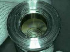
Most hot cathode ionization vacuum gauges that are currently used are B-A ionization vacuum gauges. The B-A ionization vacuum gauge collects ions using an electrode called an ion collector that is made of thin metal wires. When organic substances present in the atmosphere to be measured attach to the ion collector, they start to deposit on it because they have large activation energy for desorption and a long average residence time. Deposited organic substances form an insulator that cannot collect ions, which lowers readings 3). Figure 3 is a photograph of an ion collector that was used in a vacuum dryer. It shows carbide emitted from a work piece to be dried sticking to the ion collector.
A combination vacuum gauge that incorporates other gauges such as a Pirani vacuum gauge has become avail- able on the market. This gauge continuously measures pressure covering a much broader pressure range than ever before. This combination vacuum gauge automatically controls the filament and its high voltage using values indicated by the Pirani vacuum gauge (or whatever kind of gauge is being used), and continues operation even when the pressure is close to the upper measurable limit, which causes even more contamination of the electrode .
If readings are lowered, the equipment needs to be stopped and its chamber needs to be exposed to the atmosphere so that the gauge head can be replaced. This reduces productivity. In addition, used gauge heads are disposed of even though they contain rare metals such as tungsten, molybdenum, iridium, and platinum. More and more of these rare metals are used for electronic devices every year. Mining and smelting these materials can cause serious environmental pollution such as water and soil contamination. Rare metal prices are unstable because their mines are located in specific regions. Therefore, an increase in the frequency of replacing gauge heads not only causes a decrease in equipment productivity and increase in maintenance cost, but also damage to the environment. Also, because of the structure of these combination vacuum gauges, some normally functioning parts also need to be replaced, which is another cause of increased maintenance costs.
You can download full article with your registration
https://www.ulvac.co.jp/en/r_d/technical-journal/user_registration
For further information
https://showcase.ulvac.co.jp/en/products/vacuum-gauge/index.html?cat_m=hot-cathode-gauge
References
1) H. Yoshida: J. Vac. Soc. Jpn., 54 (2011) 483.
2) H. Akimichi: J. Vac. Soc. Jpn., 56 (2013) 220.
3) Japan patentJPWO2006/121173A1.
4) T. Nakajima, T. Miyashita, Y. Nagata, M. Fukuhara, Y.Uchida, Y. Ohasi and T. Nishimaki: ULVAC
TECHNICAL JOURNAL 76 (2012) 8.
5) M. Hirata, M. Ono,Y.Toda, K. Nakayama: Shinku, 25(1982) 372.
6) Japan patent JP5827532.
7) WO patentWO2016/139894A1.
8) WO patentWO2016/151997A1.
9) H. Yoshida: J. Vac. Soc. Jpn., 58 (2015) 155.
10) H. Yoshida: J. Vac. Soc. Jpn., 59 (2016) 237.