This post is also available in: Japanese Chinese (Simplified)
1.Introduction
Active-matrix liquid-crystal displays (AMLCDs) are popularly used to make flat panel TVs. The application of such high-definition displays led to the advent of 4K TVs, as well as smartphones with resolutions exceeding 500 ppi on the market. The pursuit of ever higher definitions is constrained by the low mobility of conventional amorphous silicon (a-Si), which makes it difficult to make larger panels with faster response at a low cost. As alternatives to a-Si, oxide semiconductors with high mobility are being explored, including the high-profile InGaZnO4 (IGZO) as reported by the group led by Hosono1-4). In addition, film deposition for making IGZO TFTs was made possible at lower temperatures by sputtering onto IGZO targets that form the channel layers. The possibility of application of this deposition technology to OLED displays and flexible displays is being discussed, going beyond the manufacture of large AMLCDs5, 6).
Research on such IGZO TFTs and prototyping of display panels are under way by numerous research groups and device manufacturers. Some models are already being mass-produced (Figure 1). One of the reasons for the limited number of items being mass produced in spite of the numerous research projects and reports is the failure to satisfy the demand for the good performance of TFTs on a large substrate in terms of uniformity and bias stability to achieve higher definition and provide advanced functions.
As a solution, the authors have developed a moving cathode that achieves high uniformity and bias stability in film deposition on large substrates. This article presents the characteristics of the moving cathode and the evaluation results of an IGZO film deposited with this cathode.

2. Deposition methods for making highly uniform IGZO films with great bias stability

(a) Distribution of film thickness
(b) Measurement result of μ-PCD.
2.1 Disadvantages of conventional cathodes
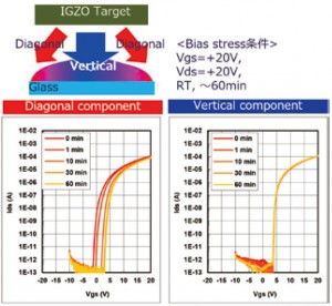
Uniform distributions of film thickness and deposition quality are essential for achieving excellent film deposition on large substrates. Parallel connection of multiple long targets, as is conventionally done with multiple cathodes, leads to a different deposition speed immediately above these targets as compared with the deposition speed between the targets, which results in uneven thickness of the film. In addition, different incident angles of sputtered particles that are deposited on substrates make the deposition quality uneven. Indeed, the stripe patterns in Figure 2 indicate the difference in the film thickness and deposition quality between the areas immediately above as well as between the targets. Figure 3 shows the reliability of a TFT made of IGZO film with the vertical component and diagonal component of incident sputtered particles that are deposited on substrates. The results demonstrate that the threshold voltage shifts positively in response to the increase in the bias stress time when deposition is exclusively performed with the diagonal component.
In contrast, such a shift is not observed when the deposition is exclusively performed with the vertical component.
In other words, a film with a large bias stability was obtained. However, with multiple cathodes there is no mechanism for controlling the incidental components of sputtered particles. Films are deposited with mixed components at various incident angles. For this reason, film deposition with conventional cathodes cannot reliably achieve a high bias stability.
2.2 Concept of the moving cathode
In order to overcome the challenges faced by conventional cathodes, a new kind of cathode, a moving cathode, has been developed by the authors according to the concept presented in Figure 4 and summarized as follows.
(1) Move a cathode over a fastened substrate to enhance uniformity and achieve a low particle count.
(2) Prepare a pre-sputtering position to hide the cathode from the substrate and thereby avoid incidence of sputtered particles to the substrate when the discharge starts and stops in order to achieve uniform deposition quality (i.e., greater bias stability) in the depth direction.
(3) Install a control plate to regulate the incident angles at which sputtered particles reach the substrate7).

2.2.1 Film deposition method
Film deposition by fastening a substrate and cathodes (stationary substrate deposition) results in an uneven surface and thickness of films because of differences in the amount of deposited sputtered particles immediately above and between targets. Scanning substrate deposition does not lead to such uneven thickness because substrates pass over a fastened cathode. Disadvantageously, however, film is not only deposited on the substrate, but also on the tray that fastens the substrate. Dust is generated when the film on the tray peels off. In contrast, scanning film deposition with a moving cathode can achieve fairly even distribution of film thickness as the cathode scans over a fastened substrate. The tray is masked during film deposition to avoid unwanted deposition, which helps to reduce the particle count.
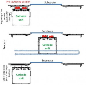
2.2.2 Pre-sputtering position
The beginning and end of a discharge pose the risks of film intrusion and plasma damage to the substrate due to ignition (Figure 5). A pre-sputtering position was installed to prevent these problems. Figure 6 presents the scanning pattern of the cathode during pre-sputtering and film deposition.

The plasma is ignited away from the substrate in order to prevent incidence of sputtered particles on the substrate at the beginning of discharge. Once the discharge stabilizes, the film is deposited on the substrate by scanning the cathode unit over it. After deposition, the discharge is terminated at the pre-sputtering position. The introduction of such a pre-sputtering position allows an even film quality to be obtained from the very beginning to the very end of the film deposition process.
2.2.3 Control of incident components
The authors evaluated incident components of sputtered particles and the corresponding TFT characteristics, keeping in mind the existing reports on incident angles of sputtered particles that are deposited on substrates and the resulting deposition quality8-10). As a result, a greater incident angle of sputtered particles proved to achieve greater bias stability in the TFTs (Figure 3).
Based on this finding, a control plate was mounted onto the moving cathode devised by the authors in order to perform film deposition with sputtered particles at a large incident angle. Figure 7 illustrates the film deposited with and without mounting the control plate onto the moving cathode. Film deposition without the control plate results in a laminated structure made of particles with both a smaller incident angle (diagonal component) and a large incident angle (vertical component). With the control plate mounted on the cathode moving over a substrate, particles with a small incident angle are blocked, enabling film deposition by particles with a large incident angle (vertical component).
